Instruction sets of a microcontroller
Instruction Set:
The set of instructions that needs to be executed by a processor in a microcontroller, which defines the fundamental operation of what can be done with this microcontroller. These instructions provide direction to the microcontroller and help it execute functions like data processing, comparison of data/actions, shifting from one part of a program to another, multiplication of registers allocated with data. And they are super powerful and flexible because ARM microcontrollers do process with the data in their registers using its instruction set.
What is Instruction Set?
A microcontroller consists of a processor with an instruction set, these are just machine-level instructions that when processed have a direct effect on the microcontroller. This is what makes these instructions the building blocks in writing software that interacts with hardware, and are important for embedded systems. ARM architecture, as an example, has a huge list of instructions like arithmetic, logical, comparison and so on commands which help in performing intelligence operations over the data.

✅ Categories of Instructions:
- Data Transfer Instructions
- Arithmetic Instructions
- Logical Instructions
- Branching (Control Transfer) Instructions
- Bit Manipulation Instructions
Most of the data processing instructions use a barrel shifter to pre-process the data of one of their operands. Each operation updates different flags in the cpsr (To learn more about ‘CPSR’ search “CPSR in ARM”).
Let us discuss the instructions in detail.
🧠 8051 Microcontroller Instruction Set Overview
The 8051 Microcontroller supports a rich set of instructions, broadly divided into:
✅ Categories of Instructions:
- Data Transfer Instructions
- Arithmetic Instructions
- Logical Instructions
- Branching (Control Transfer) Instructions
- Bit Manipulation Instructions
1️⃣ Data Transfer Instructions
Used to move data between registers, memory, and external devices.
| Instruction | Description | Example |
|---|---|---|
MOV A, #data |
Move immediate data to accumulator | MOV A, #25H → A = 25H |
MOV A, R0 |
Move register data to A | MOV A, R0 |
MOV R1, A |
Move accumulator to register | MOV R1, A |
MOV A, @R0 |
Move indirect RAM to A | MOV A, @R0 (R0 = 40H ⇒ A = RAM[40H]) |
MOV DPTR, #data16 |
Load 16-bit data to DPTR | MOV DPTR, #1234H |
MOVC A, @A+DPTR |
Read code memory | Used in lookup tables |
2️⃣ Arithmetic Instructions
| Instruction | Description | Example |
|---|---|---|
ADD A, R0 |
Add register to A | ADD A, R0 |
ADD A, #data |
Add immediate data to A | ADD A, #0AH |
ADDC A, R1 |
Add with carry | ADDC A, R1 |
SUBB A, R2 |
Subtract with borrow | SUBB A, R2 |
INC A |
Increment A | INC A (A = A + 1) |
DEC R1 |
Decrement register | DEC R1 |
MUL AB |
Multiply A & B | A = low byte, B = high byte |
DIV AB |
Divide A by B | A = quotient, B = remainder |
🔍 Example:
MOV A, #20H
MOV B, #04H
DIV AB ; A = 05H, B = 00H
3️⃣ Logical Instructions
| Instruction | Description | Example |
|---|---|---|
ANL A, R1 |
Logical AND | ANL A, R1 |
ORL A, #data |
Logical OR with immediate | ORL A, #0F0H |
XRL A, R2 |
Exclusive-OR | XRL A, R2 |
CLR A |
Clear A (A = 0) | CLR A |
CPL A |
Complement A | CPL A |
RL A |
Rotate left | RL A |
RR A |
Rotate right | RR A |
SWAP A |
Swap nibbles | High <-> Low nibble |
4️⃣ Branching Instructions
| Instruction | Description | Example |
|---|---|---|
SJMP label |
Short jump (within 128 bytes) | SJMP LOOP |
LJMP addr |
Long jump (within 64K) | LJMP 3000H |
AJMP addr |
Absolute jump | AJMP 2000H |
JZ label |
Jump if A == 0 | JZ ZERO |
JNZ label |
Jump if A ≠ 0 | JNZ AGAIN |
CJNE A, #data, label |
Compare and jump if not equal | CJNE A, #25H, NEXT |
DJNZ R0, label |
Decrement and jump if not zero | DJNZ R0, LOOP |
CALL addr |
Call subroutine | LCALL SUB1 |
RET |
Return from subroutine | RET |
RETI |
Return from interrupt | RETI |
5️⃣ Bit Manipulation Instructions
| Instruction | Description | Example |
|---|---|---|
SETB bit |
Set bit to 1 | SETB P1.0 |
CLR bit |
Clear bit | CLR P1.1 |
CPL bit |
Complement bit | CPL P1.2 |
ANL C, bit |
AND carry with bit | ANL C, P1.3 |
ORL C, bit |
OR carry with bit | ORL C, P1.4 |
MOV C, bit |
Move bit to carry | MOV C, P1.5 |
MOV bit, C |
Move carry to bit | MOV P1.6, C |
🔁 Sample Program – LED Blink using P1.0
ORG 0000H
START:
    SETB P1.0    ; Turn ON LED
    ACALL DELAY
    CLR P1.0     ; Turn OFF LED
    ACALL DELAY
    SJMP START   ; Repeat forever

DELAY:
    MOV R1, #200
L1: MOV R2, #200
L2: DJNZ R2, L2
    DJNZ R1, L1
    RET
END
📌 Notes:
- The 8051 has 128 opcodes, each 1 to 3 bytes long.
- Instructions are executed with respect to clock cycles (machine cycles).
- Common tools to simulate: Keil uVision, Proteus, MIDE-51, etc.
Comparison Instructions –
These instructions are used to compare or test a register with a 32-bit value. They update the cpsr flag bits according to the result, but do not affect other registers. After the bits have been set, the information can then be used to change program flow by using conditional execution.
Syntax – <instruction>{<cond>} Rn, N
| CMN | compare negated | flags set as a result of Rn + N |
| CMP | compare | flags set as a result of Rn – N |
| TEQ | test for quality of two 32 – bit values | flags set as a result of Rn ^ N |
| TST | test bits of a 32-bit value | flags set as a result of Rn & N |
| N is the result of the shifter operation. |
Example –
PRE
cpsr = nzcvqift_USER
r0 = 4 ; register to be compared
r9 = 4 ; register to be compared
CMP r0, r9
POST
cpsr = nzcvqift_USER output generated after comparison
5. Move Instructions –
Move is the simplest ARM instruction. It copies N into a destination register Rd, where N is a register or immediate value. This instruction is useful for setting initial values and transferring data between registers.
Syntax – <instruction>{<cond>}{S} Rd, N
| MOV | Move a 32-bit value into a register | Rd = N |
| MVN | move the NOT of the 32-bit value into a register | Rd = ~N |
Example –
PRE
r5 = 5 ; register value
r7 = 8 ; register value
MOV r7, r5 ;let r7 = r5
POST
r5 = 5 ; data in the register after moving the r5 data into r7
r7 = 5 ; output after move operation
Barrel Shifter
It is a device to shift a word with variable amount. It is one of the logic devices used to pre-process one of the operand/register before operating on to the ALU operations. And it is one of the best features of ARM.
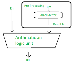
Barrel Shifter
| Mnemonics | Description | Shift | Result | Shift amount |
| LSL | logical shift left | xLSLy | x<<y | #0-31 or Rs |
| LSR | logical shift right | xLSRy | (unsigned) x>>y | #1-32 or Rs |
| ASR | arithmetic right shift | xASRy | (signed) x>>y | #1-32 or Rs |
| ROR | rotate right | xRORy | ((unsigned) x>>y) | (x<<(32 – y) | #1-31 or Rs |
| RRX | rotate right extended | xRRX | (c flag << 31) | ((unsigned) x>>1) | none |
| x represents the register being shifted and y represent the shift amount |
| N shift operations | Syntax |
| Immediate | #immediate |
| Register | Rm |
| Logical shift left by immediate | Rm, LSL #shift_imm |
| Logical shift left by register | Rm, LSL Rs |
| Logical shift right by immediate | Rm, LSR #shift_imm |
| Logical shift right by register | Rm, LSR Rs |
| Arithmetic shift right by immediate | Rm, ASR #shift_imm |
| Arithmetic shift right by register | Rm, ASR Rs |
| Rotate right by immediate | Rm, ROR #shift_imm |
| Rotate right by register | Rm, ROR Rs |
| rotate right with extend | Rm, RRX |
Example –
- This example of a MOVS instruction shifts register r1 left by one bit.
- This multiplies register r1 by a value 21
PRE
cpsr = nzcvqiFt_USER
r0 = 0x00000000
r1 = 0x80000004
MOVS r0, r1, LSL #1
POST
cpsr = nzCvqiFt_USER
r0 = 0x00000008
r1 = 0x80000004
- The C flag is updated in the CPSR because the S suffix is present in the instruction mnemonics.
Advantages of Instruction sets of a microcontroller
- Efficiency: An architectures such as that of ARM uses Reduced instruction sets (RISC) that facilitates fast and efficient operations.
- Low Power Consumption: Power consumption is typically very important in embedded systems and therefore the system has been designed with optimum power use in mind.
- Versatility: Different forms of instructions are possible to accomplish a number of operations.
Disadvantages of Instruction sets of a microcontroller
- Limited Flexibility: Some micro operations involve many instructions as the level of operation becomes high hence more complex.
- Hardware Dependent: The various microcontroller families around have their individual instruction sets something that makes them incompatible.
"This Content Sponsored by Buymote Shopping app
BuyMote E-Shopping Application is One of the Online Shopping App
Now Available on Play Store & App Store (Buymote E-Shopping)
Click Below Link and Install Application: https://buymote.shop/links/0f5993744a9213079a6b53e8
Sponsor Content: #buymote #buymoteeshopping #buymoteonline #buymoteshopping #buymoteapplication"


